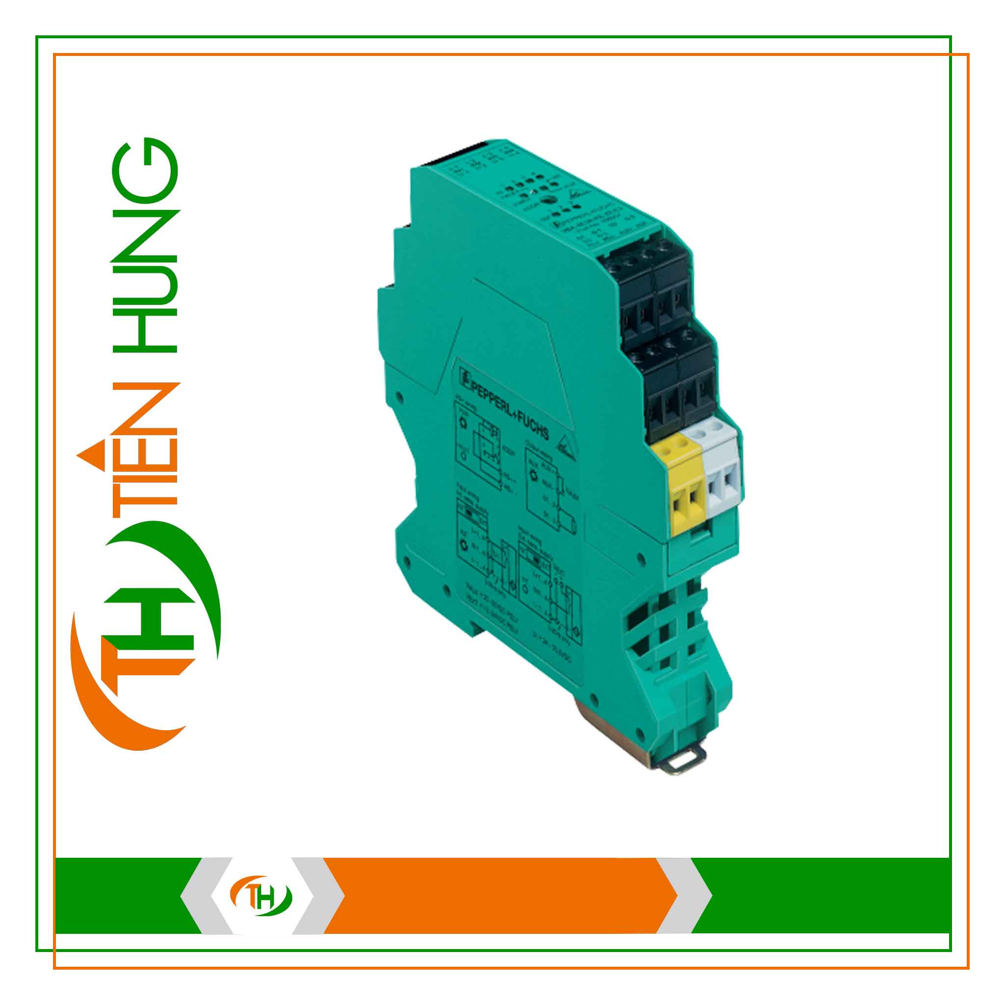
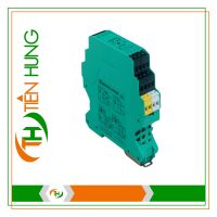
MODULE I/O VBA-4E4A-KE-ZE/R – 200913
- Technical information
- Download catalog
- Photo realistic
Indicators/Operating Means:
– LED FAULT: Displays faults; Red LED
Red: Communication fault or address is 0
Red, flashing: Overload, internal input supply
– LED INT: Indicates active internal input supply; Green LED
– LED PWR: AS-Interface voltage; Green LED
– LED IN: Switching state (input); 4 Yellow LEDs
– LED OUT: Switching state (output); 4 Yellow LEDs
Electrical Specifications:
– Auxiliary voltage (input) UEXT: 12 … 30 V DC PELV
– Rated operating voltage Ue: 26.5 … 31.6 V from AS-Interface
– Rated operating current Ie: ≤ 35 mA (no sensors)/max. 210 mA
– Surge protection O1 … O4: Over voltage category II
UEXT, Ue: Over voltage category III, safe isolated power supplies (PELV)
Input:
– Number/Type: 4 inputs for 2- or 3-wire sensors (PNP), DC
– Supply: From AS-Interface (switch position INT, default settings) or external UEXT (switch position EXT)
– Voltage: 21 … 31 V DC (INT)
– Current loading capacity: ≤ 150 mA, overload- and short-circuit protected (INT)
– Input current: ≤ 8 mA
– Signal delay: < 2 ms (input/AS-Interface)
Output:
– Number/Type: 4 relay outputs, normally open
– Supply: None
– Nominal load:
– Per contact: 2 A / 30 V DC (UL max. 24 V DC); 2 A / 253 V AC
– Per module: 8 A
– Control circuit: ≤ 8 mA per relay (from AS-Interface)
– Switching delay: < 10 ms (AS-Interface/contact)
– Switching mechanical: 5 x 10^6
– Switching electrical: 0.2 x 10^6 (250 V AC, 2 A, cos φ = 0.4)
Galvanic Isolation:
– Input/Output: Safe isolation, rated insulation voltage 300 V AC
– Input/AS-Interface:
– Switch position INT: None
– Switch position EXT: Reinforced insulation, rated insulation voltage 66 V DC
– Output/Output: Basic insulation, rated insulation voltage 300 V AC
– Output/AS-Interface: Safe isolation, rated insulation voltage 300 V AC
Purpose of Use:
The Pepperl Fuchs AS-Interface I/O module VBA-4E4A-KE-ZE/R is a control cabinet module with 4 inputs and 4 relay outputs. With a width of 22.5 mm, it occupies minimal space in the control cabinet. The module is installed by snapping onto the 35 mm DIN Rail according to EN 50022 standard.
Connections are made through plug-in slots. For inputs and outputs, 4-way terminal blocks (inputs in black, outputs in red) are used. The connection to the AS-Interface is made through a 2-way terminal block (yellow). To prevent confusion, terminals for inputs, outputs, and AS-Interface are mechanically coded.
Power supply for inputs and connected sensors can be provided either through the module’s internal supply (AS-Interface) or an external power source. Switching is done using a switch located on the side of the module. Selection of internal input supply is indicated by the LED INT. The current switching state of each input and output is indicated by the respective LED IN and OUT.
Note:
The device is equipped with communication monitoring, automatically switching outputs to their de-energized state when there is no AS-Interface communication with the module for more than 40 ms.
If the internal input supply is overloaded, a “peripheral error” message will be sent to the AS-Interface master. Communication via AS-Interface remains intact.
For 4-wire sensors, only plug-in slots IN1 or IN3 can be used for inputs 1+2 or 3+4 (internally jumpered).
Tien Hung always supports 24/7


